Validating MPPICInterFoam against sediment and particle-laden jet experiments
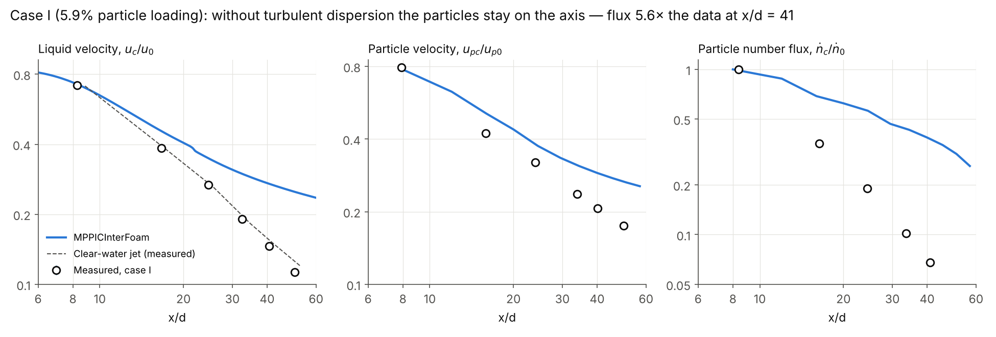
MPPICInterFoam reproduces a clear-water jet to within the measurement uncertainty, once an inlet error of ours is corrected, but it misses both sediment experiments we tested: a dense sand cloud and a dilute particle-laden jet. In the dilute jet, the particle flux on the axis at 41 nozzle diameters is 5.6 times the measured value.
MPPICInterFoam is the OpenFOAM solver that couples a VOF free surface with MPPIC Lagrangian parcels. Users pick it for dredging plumes, sediment dumping and slurry discharges. We wanted to know how far its predictions can be trusted, so we ran it against two published experiments on cloudHPC:
- A dense release: a sand cloud dropped into still water (case A7, Moghadaripour 2016).
- A dilute release: glass beads carried by a turbulent water jet (Parthasarathy & Faeth 1987).
We keep two checks apart. Verification asks whether the solver solves its equations correctly; we test it with the clear-water jet. Validation asks whether those equations describe the experiment; that is the particle comparison.
Case 1: a dense sand cloud falling in still water
The simulated sand front moves about 3 times slower than the experimental correlation, whatever mesh, injection or drag model we use.
In test A7 of Moghadaripour (2016), sand with a median diameter of 0.389 mm leaves a 10 mm nozzle for 0.252 s and falls through still water. At the exit the sand fills about 60% of the volume, so this is a dense release. The thesis fits the front depth with a power law in time (eq. 3.18).
Our setup:
- Domain: a 0.4 × 0.4 m tank about 1 m deep, refined to 3 mm (and 2 mm in one variant) around the cloud.
- Physics: LES with the Smagorinsky model, Ergun–Wen–Yu drag, explicit packing with the Harris–Crighton particle stress.
- Particles: one sand grain per parcel, normal size distribution 389 ± 40 µm.
- Variants: 3 mm mesh, 2 mm mesh, nozzle submerged to remove trapped air, and the submerged case with Wen–Yu drag.

At t/T = 10 the four variants put the front at 29 to 38 nozzle diameters; the correlation gives 93. The spread between variants is small next to that gap, so mesh, trapped air and drag are not the cause.
In every variant the cloud stays a compact clump whose front grows like the square root of time. That is how a buoyant thermal behaves, and it suggests the simulation is physically consistent. We could not confirm the correlation against independent data, so this case alone cannot tell us whether the solver or the reference is off. That is why we added a second, better documented experiment.
Case 2: a dilute particle-laden water jet
Parthasarathy & Faeth (1987) give a clean, dilute benchmark with stated uncertainties, so it isolates the particle physics.
A water jet from a 5.08 mm nozzle (32.7 ml/s) discharges downward into a 410 × 530 × 910 mm tank of still water. The jet carries 501 µm glass beads (density 2450 kg/m³). The authors measured liquid and particle velocities and particle number fluxes along the axis and across it.
| Case | Particle loading (mass) | Exit volume fraction | Exit velocity |
|---|---|---|---|
| Single phase | 0% | 0% | 1.61 m/s |
| I | 5.9% | 2.4% | 1.66 m/s |
| II | 11.8% | 4.8% | 1.72 m/s |
The stated uncertainties are 5% on mean velocities and under 15% on axial number flux.
Our setup follows the paper as closely as the solver allows:
- Mesh: 1.46 million cells, from 6.8 mm in the far tank down to 0.85 mm (6 cells per nozzle diameter) around the jet.
- Turbulence: RANS k-ε with the paper’s constants (C₂ = 1.87, σε = 1.3).
- Drag: the paper measured drag 1.5 times the standard sphere value. A Haider–Levenspiel non-spherical drag with sphericity 0.6 reproduces that factor and the measured settling velocity (0.056 against 0.05 m/s).
- Particles: injected at the nozzle with the paper’s velocity and loading, one bead per parcel, 501 ± 45 µm.
- Run: 6 s of flow, averaged from 2.5 s, on 32 cores.
One limitation shaped the result: in the ESI OpenFOAM release we tested, MPPICInterFoam offers no turbulent dispersion model for the parcels. The only option is none. Particles feel the mean liquid velocity but not its turbulent fluctuations, which matches the paper’s deterministic separated flow (DSF) model.
Results: the liquid jet passes, the particles do not
Verification: the clear-water jet
The single-phase jet decays as measured, with the centreline velocity 3–12% below the data between 9 and 53 diameters.

Most of that offset is our own error. On the stair-stepped mesh the inlet patch is 14% larger than the 5.08 mm nozzle, so for the same flow rate the water leaves at 1.41 instead of 1.61 m/s and the jet carries 6–7% less momentum. Corrected for that, the simulation sits inside the 5% band. The simulated jet half-width grows at 0.095 x, the usual value for a round jet.
Validation: the particle-laden jets
With particles the picture breaks down. Close to the nozzle (x/d ≈ 8) all three quantities match within 2%. Further down the jet, every one of them is too high.

At about 40 diameters in case I:
- the particle number flux on the axis is 5.6 times the measured value (0.38 against 0.068);
- the particle velocity is 40% too high;
- the liquid velocity is 85% too high, while the experiment shows it barely differs from the clear-water jet.
Case II, with twice the loading, is slightly worse: liquid +104%, particles +58%, flux 4.4 times the data.
Why: the beads never leave the axis
Without turbulent dispersion, nothing pushes the beads sideways. They fall in a column about 1 cm wide while the liquid jet spreads to ±5 cm.

That column then feeds back on the flow. With two-way coupling, the dense curtain of sinking glass drags the surrounding water down and keeps the centreline fast; the liquid half-width at 40 diameters shrinks from 19.5 mm to 13.3 mm. The faster liquid carries the beads further, so the error compounds. The paper’s own DSF model, which ignored this feedback, overestimated the flux at 40 diameters by about 2.5 times; MPPICInterFoam overestimates it by more than 5.
What this means if you use MPPICInterFoam
Trust the liquid, not the particle spreading. With RANS turbulence, MPPICInterFoam keeps particles where the mean flow puts them, so it overestimates concentrations on the jet axis and underestimates how far a plume spreads.
- Fine: the carrier flow, free-surface behaviour, and cases where particles follow the mean flow (very small particles, or flows dominated by settling rather than turbulence).
- Not fine without extra work: plume width, dilution and deposition footprints in turbulent jets, where turbulent dispersion sets the answer.
- Worth testing next: an LES run, where resolved eddies can scatter the parcels without a dispersion model. It needs a finer nozzle mesh and a smaller time step, so we estimate 40–60 € for one case.
What it cost on cloudHPC
| Study | Runs | Cost |
|---|---|---|
| Sand cloud A7 | 4 production runs + 3 short tests | 5.30 € |
| Particle-laden jet | 3 production runs + 2 short tests | 39.34 € |
Each particle-laden jet ran on 32 cores in 2.5 to 4.3 hours.
References
- Parthasarathy R.N., Faeth G.M. (1987). Structure of particle-laden turbulent water jets in still water. International Journal of Multiphase Flow 13(5), 699–716.
- Moghadaripour M. (2016). Experimental Study of Vertical and Oblique Particle Clouds in Water. MSc thesis, Lakehead University, Thunder Bay, Ontario.
CloudHPC is a HPC provider to run engineering simulations on the cloud. CloudHPC provides from 1 to 224 vCPUs for each process in several configuration of HPC infrastructure - both multi-thread and multi-core. Current software ranges includes several CAE, CFD, FEA, FEM software among which OpenFOAM, FDS, Blender and several others.
New users benefit of a FREE trial of 300 vCPU/Hours to be used on the platform in order to test the platform, all each features and verify if it is suitable for their needs


