MRF vs sliding mesh for a marine propeller in OpenFOAM: NCC and AMI against the PPTC towing-tank data
TL;DR
- We ran the Potsdam Propeller Test Case (PPTC, VP1304) in open water with three ways of handling rotation: MRF (steady, OpenFOAM-14), NCC non-conformal sliding mesh (OpenFOAM-14) and AMI sliding mesh (OpenFOAM v2606), all on the same 4.41 M-cell mesh, k-ω SST, 48 cores.
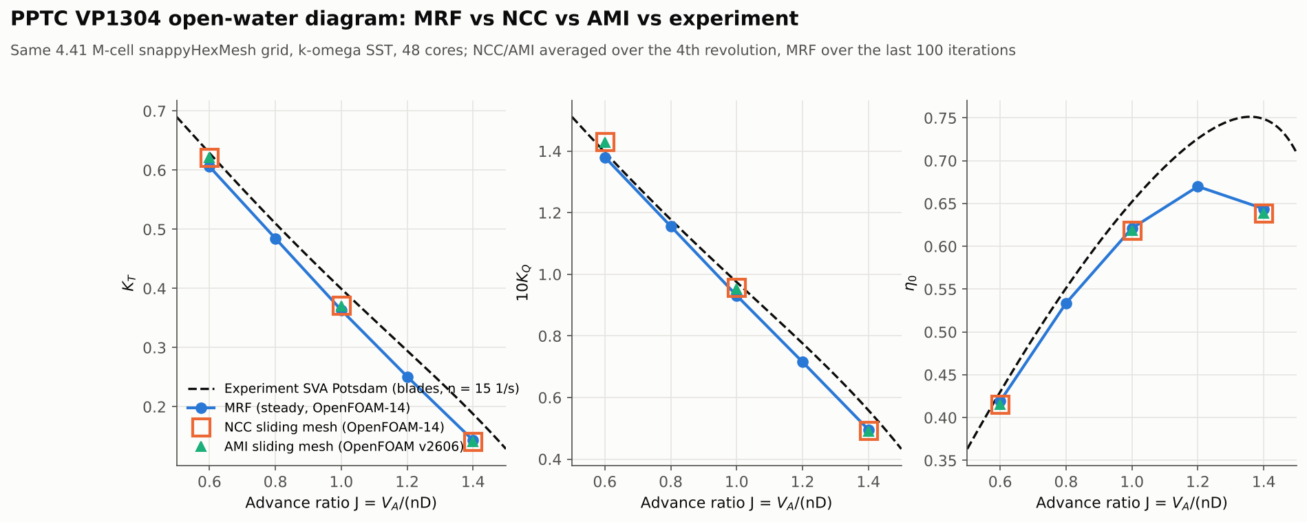
- At the design-like point J = 1.0 the thrust error versus the SVA experiment is −9.0 % (MRF), −6.9 % (NCC), −7.2 % (AMI); torque −4.5 %, −1.9 %, −2.2 %.
- NCC and AMI agree within 0.5 % on both thrust and torque at every advance ratio: two codes, two interface algorithms, one answer.
- All three methods drift together at high J (thrust ≈ −24 % at J = 1.4): the gap is in the mesh/turbulence modelling, not in how the rotation is handled.
- One operating point costs €0.91 with MRF and €8.4–10.6 with a 4-revolution sliding-mesh run on a 48-vCPU spot instance. Overset was tried and dropped; the reasons are below.

Why this comparison
Every rotating-machinery CFD job starts with the same choice: freeze the rotor in a multiple reference frame (MRF) and run steady, or actually move the mesh and pay for a transient run. OpenFOAM now offers two mature sliding-mesh interfaces that live in the two OpenFOAM distributions:
- Non-conformal coupling (NCC) in openfoam.org (released in 2022 with OpenFOAM-10 as the replacement for AMI, which was removed from that line afterwards; here OpenFOAM-14);
- Arbitrary Mesh Interface (AMI) in openfoam.com (here OpenFOAM v2606, June 2026).
We wanted three answers for cloudHPC users: how far MRF is from a sliding mesh on a real propeller, whether NCC and AMI give the same answer when fed the same mesh, and what each costs per operating point. A propeller in open water is the cleanest test bed: one rotor, axisymmetric inflow, and a public experimental data set.
Results at a glance
| J | Quantity | Experiment | MRF (of14) | NCC (of14) | AMI (v2606) |
|---|---|---|---|---|---|
| 0.6 | KT | 0.6288 | 0.6060 (−3.6 %) | 0.6218 (−1.1 %) | 0.6209 (−1.3 %) |
| 10KQ | 1.3964 | 1.3804 (−1.1 %) | 1.4304 (+2.4 %) | 1.4279 (+2.3 %) | |
| η0 | 0.430 | 0.419 (−2.5 %) | 0.415 (−3.5 %) | 0.415 (−3.4 %) | |
| 1.0 | KT | 0.3994 | 0.3635 (−9.0 %) | 0.3719 (−6.9 %) | 0.3706 (−7.2 %) |
| 10KQ | 0.9749 | 0.9313 (−4.5 %) | 0.9568 (−1.9 %) | 0.9530 (−2.2 %) | |
| η0 | 0.652 | 0.621 (−4.7 %) | 0.619 (−5.1 %) | 0.619 (−5.1 %) | |
| 1.4 | KT | 0.1878 | 0.1433 (−23.7 %) | 0.1415 (−24.7 %) | 0.1409 (−25.0 %) |
| 10KQ | 0.5588 | 0.4958 (−11.3 %) | 0.4937 (−11.7 %) | 0.4916 (−12.0 %) | |
| η0 | 0.749 | 0.644 (−14.0 %) | 0.639 (−14.7 %) | 0.639 (−14.7 %) |
Blades-only forces, n = 15 1/s. MRF: mean of the last 100 of 500 iterations per J. NCC and AMI: mean over the 4th revolution (360 time steps). MRF was also run at J = 0.8 and 1.2 (KT 0.4846 / 0.2510, −5.0 % / −14.9 %).

The test case: PPTC VP1304

The Potsdam Propeller Test Case is the controllable-pitch propeller VP1304 of SVA Potsdam, released with geometry and towing-tank data for the smp’11 Propeller Workshop (Second International Symposium on Marine Propulsors, Hamburg, 2011).
| Item | Value |
|---|---|
| Propeller | VP1304, D = 0.25 m, Z = 5 blades, P0.7/D = 1.635, right-handed |
| Rotation | n = 15 1/s (ω = 94.25 rad/s about +x) |
| Fluid (smp’11 prescription) | ρ = 998.67 kg/m³, ν = 1.070 × 10⁻⁶ m²/s |
| Advance ratios | J = VA/(nD) = 0.6, 1.0, 1.4 (MRF also 0.8 and 1.2) |
| Reference | SVA open-water test, n = 15 1/s, blades only (corrected for hub resistance and idle torque); smp’11 Case 2.1 polynomials |
| Geometry | SVA STEP file with closed hub fillets, tessellated with OpenCASCADE into blades / hub / cap / shaft regions; shaft extended to the outlet |
| Domain | box 9D long (3D upstream, 6D downstream) × 6D × 6D, slip side walls, fixed velocity inlet, fixed pressure outlet |
| Rotating zone | cylinder r = 0.15 m (0.6D), x = −0.0265…0.15 m, interface inside the 3 mm gap between hub and shaft fairing |
Forces are integrated on the blades only, as in the reference data: KT = T/(ρn²D⁴), KQ = Q/(ρn²D⁵), η0 = J KT/(2π KQ).
How the runs were set up
| MRF | NCC | AMI | |
|---|---|---|---|
| Distribution / version | OpenFOAM-14 (openfoam.org) | OpenFOAM-14 (openfoam.org) | OpenFOAM v2606 (openfoam.com) |
| Solver | foamRun, incompressibleFluid, steady SIMPLE, MRFProperties | foamRun, incompressibleFluid, PIMPLE, solidBody rotation | pimpleFoam, dynamicMotionSolverFvMesh, solidBody rotation |
| Interface | none (rotor cellZone) | createBaffles → splitBaffles → createNonConformalCouples (89,666 couplings over 43,961 + 43,961 faces) | createBaffles → cyclicAMI pair, 43,961 + 43,961 faces, lowWeightCorrection 0.2 |
| Mesh | the same snappyHexMesh (OpenFOAM-14) grid: 4,408,036 cells, base cell 0.06 m, blades level 7 (≈0.47 mm), 4 prism layers on blades/hub/cap, rotor zone level 4 | ||
| Time / iterations | 500 iterations per J (one job: inlet velocity stepped every 500 iterations; inlet k and ω kept at the J = 1.0 values) | Δt = 1° of rotation (1.852 × 10⁻⁴ s), 4 revolutions = 1,440 steps, 2 outer × 2 pressure correctors | |
| Start | uniform flow | impulsive start | rotation speed ramped 0 → 15 1/s over 0.25 rev; correctPhi on |
| Common: k-ω SST, Spalding wall function (blade y+ ≈ 27 on average), inlet turbulence 1 %, νt/ν = 1, linearUpwind for U, upwind for k and ω, GAMG for pressure. | |||
| Instance | cloudHPC hypercore, 48 vCPU = 48 physical cores (AMD EPYC 9B45), spot pricing, one MPI rank per core | ||
Using one mesh for all three methods was deliberate (and, as told below, also the fix for the AMI runs): the differences in the table above come from the rotation model and the code, not from meshing.
Case 1 — MRF: cheap, and 9 % short on thrust at J = 1.0
A full MRF open-water curve (five advance ratios, 2,500 iterations in one job) took 41 minutes of solver time at 0.99 s per iteration and cost €4.56 including meshing, boot and upload. Each window had settled: KT changed by at most 0.0005 (0.1 %) between the last two blocks of 100 iterations.
The accuracy is good at high load (J = 0.6: thrust −3.6 %, torque −1.1 %) and degrades as the load drops (J = 1.4: −23.7 % / −11.3 %). Before blaming MRF we tried to close the gap at J = 1.0:
| Variant (J = 1.0, MRF unless noted) | Cells | KT | err KT | 10KQ | err 10KQ | blade y+ (avg) |
|---|---|---|---|---|---|---|
| Medium grid, 1,500 iterations | 4,408,036 | 0.3635 | −9.0 % | 0.9313 | −4.5 % | 27 |
| Fine grid (base 0.048 m), 800 iterations | 7,143,796 | 0.3630 | −9.1 % | 0.9290 | −4.7 % | 22 |
| Medium + distance refinement around the blades | 6,242,185 | 0.3640 | −8.9 % | 0.9327 | −4.3 % | 27 |
| 12 prism layers, first cell 5 µm, k-ω SST | 4,591,336 | 0.3661 | −8.3 % | 0.9289 | −4.7 % | 14 |
| 12 prism layers, k-ω SST-LM (transition) | 4,591,336 | 0.3745 | −6.2 % | 0.9313 | −4.5 % | 13 |
| NCC sliding mesh, medium grid, 4 rev | 4,408,036 | 0.3719 | −6.9 % | 0.9568 | −1.9 % | — |
| AMI sliding mesh, medium grid, 4 rev | 4,408,036 | 0.3706 | −7.2 % | 0.9530 | −2.2 % | — |

What we learned. Iterating longer, a finer grid and refinement around the blades move MRF thrust by 0.13 points at most: the result is grid-independent for this wall-function set-up. A 12-layer near-wall grid moves it 0.7 points. Two things move it more: a transition model (SST-LM on the 12-layer grid, a further +2.1 points, −6.2 % in total) and moving the mesh (+2.1 points with NCC, +1.8 with AMI on the original grid), and at J = 1.0 the sliding mesh also halves the torque error. Note that the 12-layer grid aimed at y+ ≈ 1 reached an average of only 13–14 because snappyHexMesh did not grow all the layers: a proper low-Re grid remains an open item.
Case 2 — NCC sliding mesh (OpenFOAM-14)
The openfoam.org route is: snappyHexMesh with the rotor cylinder as an internal faceZone, createBaffles and splitBaffles to open it, renumberMesh, then createNonConformalCouples nonCouple1 nonCouple2, which built 89,666 couplings between the two 43,961-face sides in about a second. The rotor moves with a solidBody / rotatingMotion mover.
| J | KT | 10KQ | η0 | err KT / 10KQ / η | Solver time (1,440 steps) | s per step | Billed cost |
|---|---|---|---|---|---|---|---|
| 0.6 | 0.6218 | 1.4304 | 0.4151 | −1.1 / +2.4 / −3.5 % | 5,970 s | 4.15 | €9.73 |
| 1.0 | 0.3719 | 0.9568 | 0.6186 | −6.9 / −1.9 / −5.1 % | 6,211 s | 4.31 | €10.09 |
| 1.4 | 0.1415 | 0.4937 | 0.6386 | −24.7 / −11.7 / −14.7 % | 6,386 s | 4.43 | €10.59 |
With an impulsive start the thrust overshoots and settles within one to two revolutions; the mean KT of the last two half-revolutions differs by less than 0.0003 at every J. In the 2-revolution sizing run (€5.52) the last two half-revolutions still differed by 0.0009, which is why the production runs used four (the 2nd-revolution mean was in the end only 0.15 % above the 4th-revolution value).

Case 3 — AMI sliding mesh (OpenFOAM v2606): the same answer, after three false starts
The final AMI runs used the OpenFOAM-14 mesh read into v2606, createBaffles to make a matching cyclicAMI pair (weights 0.99–1.11 at start; as the rotor turns, faces next to the shaft–fairing gap become partly uncovered, weights range 0–1.93, and lowWeightCorrection 0.2 handles them), correctPhi yes, and a 0.25-revolution ramp of the rotation speed.
| J | KT | 10KQ | η0 | err KT / 10KQ / η | Solver time (1,440 steps) | s per step | Billed cost |
|---|---|---|---|---|---|---|---|
| 0.6 | 0.6209 | 1.4279 | 0.4152 | −1.3 / +2.3 / −3.4 % | 5,235 s | 3.64 | €8.38 |
| 1.0 | 0.3706 | 0.9530 | 0.6189 | −7.2 / −2.2 / −5.1 % | 5,590 s | 3.88 | €8.91 |
| 1.4 | 0.1409 | 0.4916 | 0.6385 | −25.0 / −12.0 / −14.7 % | 5,590 s | 3.88 | €8.87 |
AMI and NCC differ by at most 0.45 % in KT and 10KQ (0.4 points or less on the error versus experiment). AMI was 10–13 % faster per time step here, with the caveat that the two runs use different solver applications and builds.
Getting there took four mesh/numerics set-ups, all visible in the cloudHPC logs:
- snappyHexMesh
faceType boundary+createPatch(the shortcut): the two sides of the interface came out different (38,470 vs 36,199 faces) because snappy merges refined boundary faces on one side only. AMI weights ranged from 0 to 2.7 and the run blew up (max Courant 35 → 4,445 → 10¹⁰⁵, floating-point exception in GAMG after 74–78 time steps). Cost €3.51 and €4.34; the J = 0.6 run did not diverge but was discarded (€8.07). - Internal faceZone +
createBaffles(as in the ESI propeller tutorial): matching sides (44,159 faces each, weights 1.0–1.1), but withcorrectPhi noand an impulsive start it diverged at step 3. correctPhi yes+ 0.25-revolution ramp on the v2606 snappyHexMesh grid: diverged at step 19 with the rotor still almost at rest. The Courant number jumped to 154 at step 2, which points at a few poor cells in that grid (31 faces above 70° non-orthogonality, 6 highly skewed faces), not at AMI.- The OpenFOAM-14 grid in v2606: stable from the first step (J = 1.0: max Courant 28 at start, 71 after the first step, 23–59 during the ramp and 43–50 at full speed; up to 98 after the first step at J = 1.4). Two practical notes:
rotatingMotionintegrates ω(t), and v2606 refuses to integrate atablebeyond its last point, so the ramp table needs a final point far in the future; and cloudHPC unpacks any archive in an uploaded case, so a mesh shipped as.tar.gzinside the case must be renamed (we used.bin) and unpacked by the Allrun.
What didn’t work: overset (OpenFOAM v2606)
The plan included overset (overPimpleDyMFoam) as a third moving-mesh option. We dropped it, and the reasons are worth sharing.
| # | Configuration (coarse grid, ~1 M cells, one to five steps) | Background cells outside the component | Outcome |
|---|---|---|---|
| 3 | Overset interface at x = −0.0265 m (same as MRF/NCC), inverseDistance, search box around the rotor | ~145 k of 162 k flagged as hole | runs, but the outer flow is not computed |
| 4 | as 3, search box = whole domain | 142 k hole | search box not the cause |
| 5 | as 4, component walls made watertight | 143.8 k hole, FPE at step 4 | closed walls not the cause |
| 6–7 | interface moved to x = −0.20 m, fairing front inside the component (static, U = 0) | 0 calculated, 0.4 k interpolated, 121.3 k hole | hole filling inverted |
| 8b | as 7, trackingInverseDistance | 0 calculated, 121.1 k hole | same inversion |
| 8c | as 7, inverseDistance + holeLayers 4; useLayer 2 | 0 calculated, 121.2 k hole | same inversion |
| 8a | as 7, cellVolumeWeight | 121,459 calculated, 0 hole | correct cell types |


On this geometry, where the shaft and fairing walls cross the overset boundary, the three voxel-based hole-cutting methods invert the fill. The geometric-overlap method cellVolumeWeight gets it right, but on the medium grid (4.97 M cells, 48 cores) it cost 155 s per time step, about €80 per revolution at 1° per step, and the run was unstable from the first step (max Courant 61 → 6.5 × 10¹⁷, floating-point exception at step 9). Total spent on the overset trials: ≈ €4.8. An overset propeller remains possible with the shaft entirely in the background mesh and a larger time step; that is a separate study.
Run times and costs
| Block | What | Billed cost |
|---|---|---|
| MRF | open-water curve, 5 J, one job | €4.56 |
| MRF | sizing + 5 diagnostic variants at J = 1.0 | €20.92 |
| NCC | 3 production runs (4 rev) + 2-rev sizing | €35.93 |
| AMI | 3 production runs (4 rev) | €26.16 |
| AMI | failed attempts, of14 mesh export, test | €22.35 |
| Overset | tutorial copy, 10 smoke tests, medium run | €4.76 |
| Other | geometry download job | €0.05 |
| Whole campaign | €114.72 | |

Per operating point the picture is simple: MRF ≈ €0.91 (one-fifth of the polar job), NCC ≈ €10.1, AMI ≈ €8.7 on a 48-vCPU hypercore spot instance (about €5.3 per hour for the whole machine). Billed cost includes boot, meshing (3–4 min), end-of-run detection and result upload.
Right tool for the job: use MRF to sweep an open-water curve or to screen designs: it is ten times cheaper, and at heavy load (J = 0.6) it is within 3.6 % on thrust and 1.1 % on torque. Use a sliding mesh (NCC or AMI, whichever distribution you already use) near the design point, where it cut the J = 1.0 errors from 9.0 % to 6.9 % on thrust and from 4.5 % to 1.9 % on torque, and whenever you need unsteady blade loads or rotor–stator interaction. Neither fixes the high-J thrust deficit on this grid: that needs a finer near-wall resolution or a transition model.
How to run this on cloudHPC
- Solver entries:
openFoam-of14(MRF, NCC) andopenFoam-v2606(AMI). With anAllrunscript in the case root cloudHPC runs it instead of the standard sequence; numberOfSubdomains is set to the physical cores. - Instances: OpenFOAM needs hypercore or highcore (one MPI rank per physical core). Spot instances are fine: with
startFrom latestTimea preempted run restarts from the last write. - OpenFOAM-14 specifics: controlDict needs
application foamRun; solver incompressibleFluid;; mesh utilities overwrite by default; after a parallel snappyHexMesh decompose fields withdecomposePar -fields -copyZero. - NCC sequence:
createBaffles,splitBaffles,renumberMesh,createNonConformalCouples nonCouple1 nonCouple2, in parallel. - AMI: keep the rotor faceZone internal in snappyHexMesh and split it with
createBafflesinto acyclicAMIpair; check that both sides have the same face count incheckMeshbefore running. - Mesh reuse across distributions: an openfoam.org polyMesh can be read by v2606 after editing the zone headers (
cellZoneList/faceZoneList→regIOobject) and addingtype cellZone;/type faceZone;to each zone entry. - Archives: do not ship a
.tar.gzinside the case folder unless you want cloudHPC to unpack it at upload. - The full inputs and the Python scripts that generate every case are in the download package of this post.
FAQ
Is MRF accurate enough for a marine propeller in OpenFOAM? For open-water curves at medium-to-high load, yes: on PPTC it was within 3.6 % on thrust and 1.1 % on torque at J = 0.6, and within 9 % / 4.5 % at J = 1.0. Its error grows at light load, but so did the sliding-mesh error on the same grid.
What is the difference between NCC and AMI in OpenFOAM? Both couple two non-matching mesh regions that slide past each other. NCC (non-conformal coupling) is the openfoam.org implementation, introduced in 2022 as the replacement for AMI, and builds explicit couplings between the two sides; AMI (arbitrary mesh interface) is the openfoam.com implementation based on interpolation weights. On the same mesh they gave the same propeller thrust and torque within 0.5 %.
How many revolutions does a sliding-mesh propeller run need? Here, with 1° per time step, thrust settled within one to two revolutions and the 4th revolution was used for averaging. After two revolutions the mean thrust was already within 0.2 % of the final value, but still drifting slightly.
Why does my AMI propeller case diverge in the first time steps?
Check that both AMI patches have the same number of faces and that the weights are close to 1 (they are printed at start-up). We saw divergence with non-matching sides from snappyHexMesh faceType boundary, without correctPhi, and with a few poor cells near the interface. A short ramp of the rotation speed helps.
Can I use overset for a propeller with a shaft?
In our tests with OpenFOAM v2606, when the shaft and fairing crossed the overset boundary the voxel-based hole-cutting methods inverted the hole map; cellVolumeWeight worked but was about 40 times slower per step than the sliding mesh and unstable. Check the cellTypes field after one step before committing to a long run.
References
- SVA Potsdam, PPTC smp’11 Workshop: geometry, test reports and evaluation — https://www.sva-potsdam.de/en/pptc-smp11-workshop/
- SVA Potsdam, Report on Open Water Tests, SVA Report 3752 (propeller VP1304) — https://www.sva-potsdam.de/wp-content/uploads/2016/04/SVA_report_3752.pdf
- smp’11 Propeller Workshop, Case 2.1: Open Water Tests (evaluation of the submitted results) — https://www.sva-potsdam.de/wp-content/uploads/2016/03/smp11_case21_eval_OWT.pdf
- CFD Direct, Using non-conformal coupling (OpenFOAM) — https://cfd.direct/openfoam/free-software/using-non-conformal-coupling/
- OpenFOAM Foundation, OpenFOAM 14 released — https://openfoam.org/release/14/
- OpenCFD, OpenFOAM v2606 release — https://www.openfoam.com/news/main-news/openfoam-v2606
- Turunen, T., Siikonen, T., Lundberg, J. and Bensow, R. (2014), Open-water computations of a marine propeller using OpenFOAM, ECFD VI, Barcelona, pp. 1123–1134 — https://research.chalmers.se/en/publication/201623
- Mühlhölzer, R. (2012), Feasibility Study on the Use of Multiple-Reference Frames for Computations of Propeller-Hull Interaction in OpenFOAM, MSc thesis, Chalmers — https://odr.chalmers.se/items/fa3fbb37-77d9-4407-be9e-8fdb7f9edcb2
CloudHPC is a HPC provider to run engineering simulations on the cloud. CloudHPC provides from 1 to 224 vCPUs for each process in several configuration of HPC infrastructure - both multi-thread and multi-core. Current software ranges includes several CAE, CFD, FEA, FEM software among which OpenFOAM, FDS, Blender and several others.
New users benefit of a FREE trial of 300 vCPU/Hours to be used on the platform in order to test the platform, all each features and verify if it is suitable for their needs


