Align meshes in Blender FDS
Meshes define the computational domain of your simulation. Multiple meshes are useful to assign the work load to different cores, achieve a good scalability and optimize the simulation. However, it is fundamental to properly aligned abutting meshes in order to be able to run the simulation. Blender FDS tool is a useful tool to quickly align multiple meshes.
Generally, finer meshes are chosen where you need detailed calculations. Such as where fire spread, fire growth, high temperatures and velocities occurs. While coarser meshes are used where less detailed calculation are needed. In this way you reduce the number of cell and therefore the simulation time.
More posts are available in the Blog about FDS Mesh, such as:
- How to calculate the FDS mesh size: FDS Mesh Resolution: How to calculate FDS mesh size ;
- How to divide meshes in FDS and assign them to MPI processes. FDS meshing using the MPI PROCESS: a little guide ;
- How to split FDS meshes in Blender FDS and assign MPI Processes : Split FDS Mesh using BlenderFDS ;
- How to reach good scalability in FDS ;
- MultiCORE vs MultiThread – a little guide.
Mesh Alignment Rules of Thumb
However, the meshes must be correctly aligned to share the information from a cell to the other. Thus, the following rules of thumb should be followed when setting up multiple meshes, as shown by the FDS User Guide:
- Abutting cells must have the same cross sectional area, or integral ratios; as shown in Fig. 6.2 of the FDS User Guide. Therefore, in the following image the first two examples are allowed when aligning multiple meshes, while the last alignment is not allowed.

- It is fundamental to avoid putting mesh boundaries where critical action is expected, such as where fire spread and growth occur. As a matter of fact, the exchange of information across mesh boundaries is not as accurate as cell to cell exchanges within one mesh.
- The information is only exchanged at exterior of the cells. Therefore, generally is preferable to isolate the detailed fire behavior within one finer mesh, and set coarser meshes at the exterior boundary of the fine mesh. The fine and coarse meshes will mutually exchange information. Overlapping meshes are allowed, as shown in the first example below. But its usefulness is questionable since the information will be exchanged only at the exterior boundaries. While the second situation is not allowed since each large cell must be completely covered by small ones.

- To make sure that each mesh take account the obstructions, avoid to have a planar obstruction close to two meshes boundaries. If the obstruction is not inside one of the meshes, then that mesh will not consider the presence of the obstruction in the simulation.
To check the mesh alignment you can set CHECK_MESH_ALIGNMENT to T on any MESH line. If the job stops with no errors, the meshes obey the alignment rules.
How to align multiple Meshes in Blender FDS
Once you have designed multiple meshes in Blender FDS of different dimensions in order to define the computational domain of the simulation, you must correctly align the meshes following the criteria exposed above.
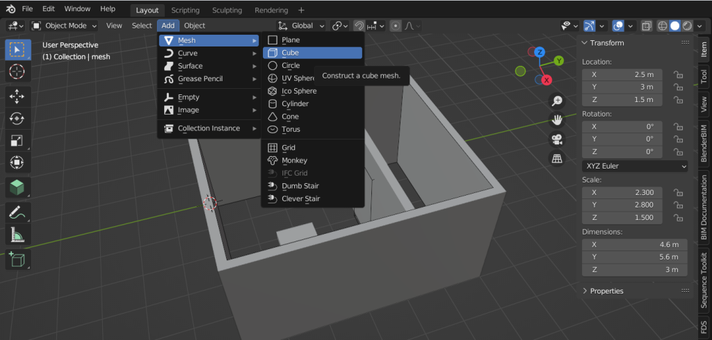
To create new meshes you can simply click on “Add”, then “mesh” and “cube”. The, using the transform item on the right you will be able to size the mesh of the wanted dimension.
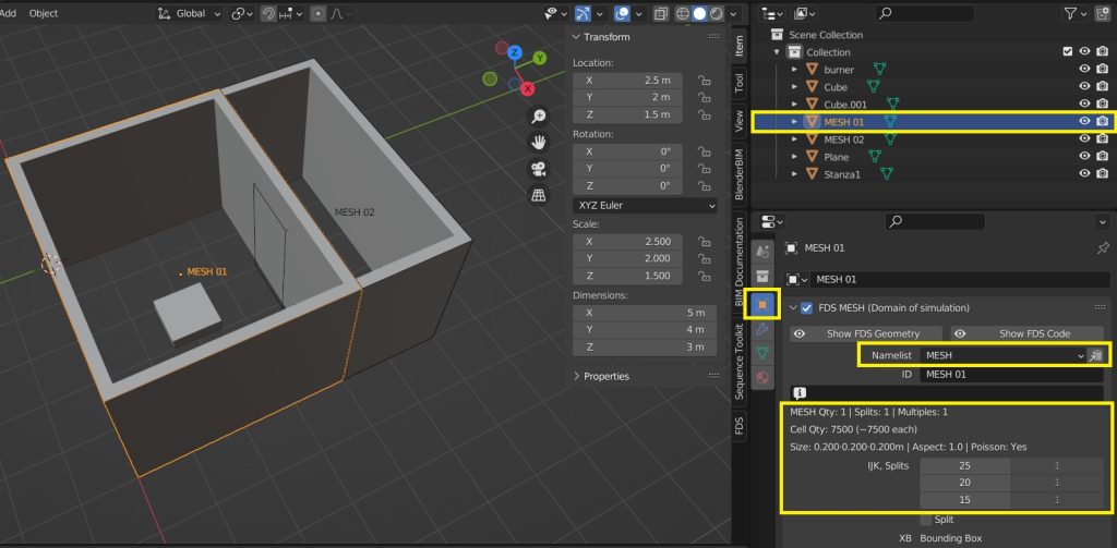
Select the object created and assign the namelist MESH form the “Object Properties” . For here it is possible to define the number and size of the cells by indicated the IJK splits. The IJK Splits allows you to set the number of cells you will get along the x, y and z axis. In this case showed the Mesh 01 will have 7500 cells each of 0,2×0,2×0,2m.
Now, we want to align the second abutted mesh named Mesh 02 to Mesh 01. In order to do so, select first the mesh you want to align (Mesh 02) and then the mesh you want to align to (Mesh 01). Then go to FDS window and click on “Align Selected”.
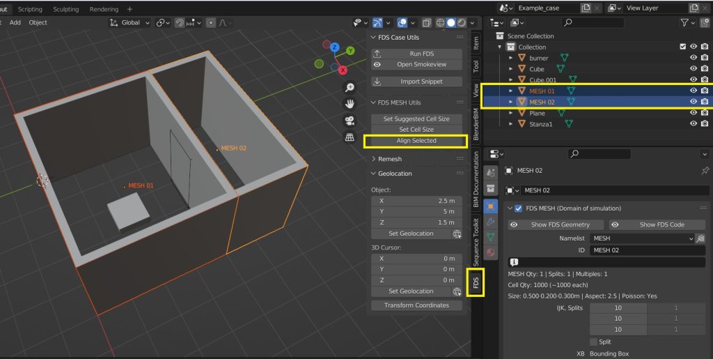
In order to work, the cells of Mesh 02 must be coarser than Mesh 01 before aligning them. Blender will align only the axis shared between both meshes. Mesh 02 cells will be adjusted to the most approximated multiple value that can be aligned to the cell of Mesh 01. For example, if the size of Mesh 01 cell is 0,2m and the size of Mesh 02 cell is 0.85, the Mesh 02 cells will become 0.8 wide since is the most approximate multiple value of 0.2.
CloudHPC is a HPC provider to run engineering simulations on the cloud. CloudHPC provides from 1 to 224 vCPUs for each process in several configuration of HPC infrastructure - both multi-thread and multi-core. Current software ranges includes several CAE, CFD, FEA, FEM software among which OpenFOAM, FDS, Blender and several others.
New users benefit of a FREE trial of 300 vCPU/Hours to be used on the platform in order to test the platform, all each features and verify if it is suitable for their needs


0 Comments