FDS Mesh Resolution: How to calculate FDS mesh size
In FDS, the calculations are performed within the set-up domain defined by the meshes. A mesh is a volume formed by rectangular cells. The number and size of the cells define the desired resolution of the mesh and therefore of the calculations.
This post aim to give an overview about FDS meshes and how to properly size them. Moreover, it is shown a generally accepted method to calculate the mesh grid resolution in the order for coarse, medium, and fine resolution. A FDS mesh size online calculator is also available.
FDS Mesh
In FDS is possible to set the domain with the namelist MESH as shown as follow:
&MESH IJK=10,20,30, XB=0.0,1.0,0.0,2.0,0.0,3.0 /The parameter IJK represent the numbers of cell through the directions I, J and K.
It is fundamental that the geometry, formed by obstructions, vents ecc.., are designed within the boundaries of the mesh. If not those element will not be considered in the calculation domain. Generally, it is recommended to dimension the mesh cells so as to approximate a cubic shape.
Since the FDS pressure solver employs Fast Fourier Transforms in y and z directions, it is more efficient if the number of cells in these directions (J and K) can be factored into low primes, like 2, 3, and 5.
Multiple Meshes
In FDS it is possible to use multiple meshes. Therefore, the computational domain considers more than one mesh, usually connected to each other. Each mesh is defined by its own MESH line. When two meshes connects, it allows the communication of calculations and results between each other.
Using multiple meshes can be useful in order to :
- concentrate the finest calculations where most needed. For example, where the fire ignites or where the velocity of the air and smoke is higher, e.g. near vents;
- if the geometry is complex, the use of multiple meshes allows you to tailor the calculation domain to your geometry and avoid wasting calculation capacity and time;
- you can run FDS in parallel using MPI (Message Passing Interface) assigning each mesh to a specific MPI process and therefore to a CPU. In this way, you can tailor the computational capacity to your meshes depending on the number and size of cells, and therefore divide the workload among the available computers. Finally, you can optimize your calculation and reduce the simulation time.
FDS Mesh Alignment
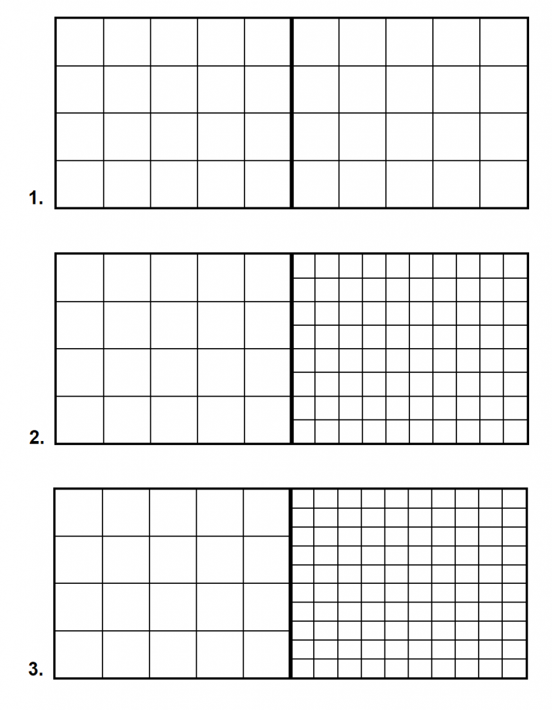
The main rule of mesh alignment is that abutting cells must have the same cross sectional area, or integral ratios. The FDS User Guide, paragraph 6.3, gives a clear overview and easy to understand examples, reported as follow:

The first two images show ideal and allowed alignments, while the third alignment is not allowed.
It is important to avoid putting mesh boundaries where critical action is expected, such as where the fire occurs. The exchange of information across mesh boundaries is not yet as accurate as cell to cell.
When designing the mesh alignments, the user should assess if the loss of information from a fine to a coarse mesh, for example cause by too much gap in cell size from one mesh to another, is tolerable.
Mesh Resolution
When defining the mesh resolution, generally it is recommended to perform a mesh sensitivity study. For instance, you can start using a relatively coarse mesh, and then gradually refine it until you do not see appreciable differences in your results.
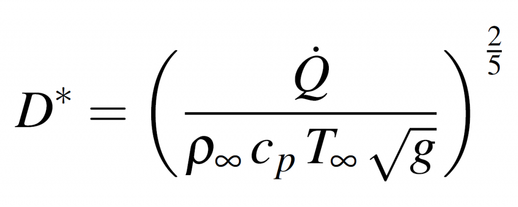
The FDS Guide gives a method to size the mesh grid, for simulations involving buoyant plumes, which depends on the characteristic fire diameter, given by the non-dimensional expression:

Where:
- Q is the total heat release rate of the fire
- p∞ is the air density (kg/m3)
- cp is the air specific heat (kJ/kg K)
- g is the gravitational constant (m/s2)
- T∞ is the ambient temperature (K)
The quantity D*=dx can be considered as the number of computational cells covering the characteristic diameter of the fire. The more cells spanning the fire, the better the resolution of the calculation.
The FDS User Guide suggests a D*/dx ratio of 4 for the coarse mesh, 10 for the medium one and 16 for the fine, where dx is the cell size.
Mesh size online calculator
A mesh calculator is available online at the following website. The original mesh calculator was developed by Kris Overholt and now it is maintained by Salah Benkorichi.
The Mesh size calculator, automatically calculates the optimal (Poisson-friendly) mesh division numbers and returns a complete MESH line to be used in an FDS input file. The cell sizes are determined using the characteristic fire diameter and cell size ratio depending on the total heat release rate of you fire simulation.
Running complex simulation with fine cell’s size will take a great amount of simulation time and computation capacity. For this reason, it is generally suggested to take advantage of Cloud Computing Services. Thanks to CLOUD HPC you can use the power of a cluster to run your engineering analyses. Directly select from the webapp the amount of CUP and RAM needed to run and speed up your simulations. If interested, you can register here and get 300 free vCPU/hrs.
References
K. Mcgrattan et al, “Fire Dynamics Simulator User’s Guide Sixth Edition,” 2019
CloudHPC is a HPC provider to run engineering simulations on the cloud. CloudHPC provides from 1 to 224 vCPUs for each process in several configuration of HPC infrastructure - both multi-thread and multi-core. Current software ranges includes several CAE, CFD, FEA, FEM software among which OpenFOAM, FDS, Blender and several others.
New users benefit of a FREE trial of 300 vCPU/Hours to be used on the platform in order to test the platform, all each features and verify if it is suitable for their needs


1 Comment
Align meshes in Blender FDS - Cloud HPC · 19 May 2023 at 2:40 pm
[…] How to calculate the FDS mesh size: FDS Mesh Resolution: How to calculate FDS mesh size ; […]
Comments are closed.