JetFan model in FDS

Jet Fans are commonly elements present in car parks. They are elements whose goal is moving air, smoke and heat in case of fire towards an extraction point. JetFan model is FDS is a strategic choice when running a fire scenario.
Jet Fans applications is quite common in indoor car parks because of their little requirements in terms of constructions (they are a sort of plug-and-play system) and easy maintenance.
When dealing with fire preventions systems, CFD software such as FDS allows designers to generate a model for this technical equipments. These models can be easy or complex depending on the type of jet fans we want to model and the accuracy we need to reach.
In this blog post we are going to investigate two of the most commont modelling for jet fans which are allowed by FDS.
Method 1 – DEVC
The first jetfan model in FDS is the easies method and can be used when representing axial jet fans. This model can be implemented with few lines but it can be only applied to axial jet fans aligned with one of the axis of the reference system.
# JET FANS - Method 1
&DEVC ID='JFAN1_devc', XYZ=0,0,0, QUANTITY='TIME', SETPOINT=20 /
&PROP ID='jf1', VELOCITY_COMPONENT=1, P0=12 /
&DEVC ID='jetfan' XB=-1,1,-0.2,0.2,3.4,3.8, QUANTITY='VELOCITY PATCH', PROP_ID='jf1' , DEVC_ID='JFAN1_devc' /
In the above formula we have three FDS commands which are defining the jet fan behaviour:
- DEVC -> the first DEVC defines a SETPOINT of 20s. Before this time the jet fans is not operative, after this it starts generating thrust
- PROP -> definition of the properties of the jet fans. VELOCITY_COMPONENT tells along which axis the jet fans is operative (options are +/- 1 for the X axis, +/- 2 for the Y and +/- 3 for the Z one) and the air velocity it is generating expressed in m/s
- DEVC -> the second DEVC defines the jet fan locations with XB and connect the earlier definition in one single element.
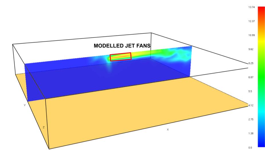
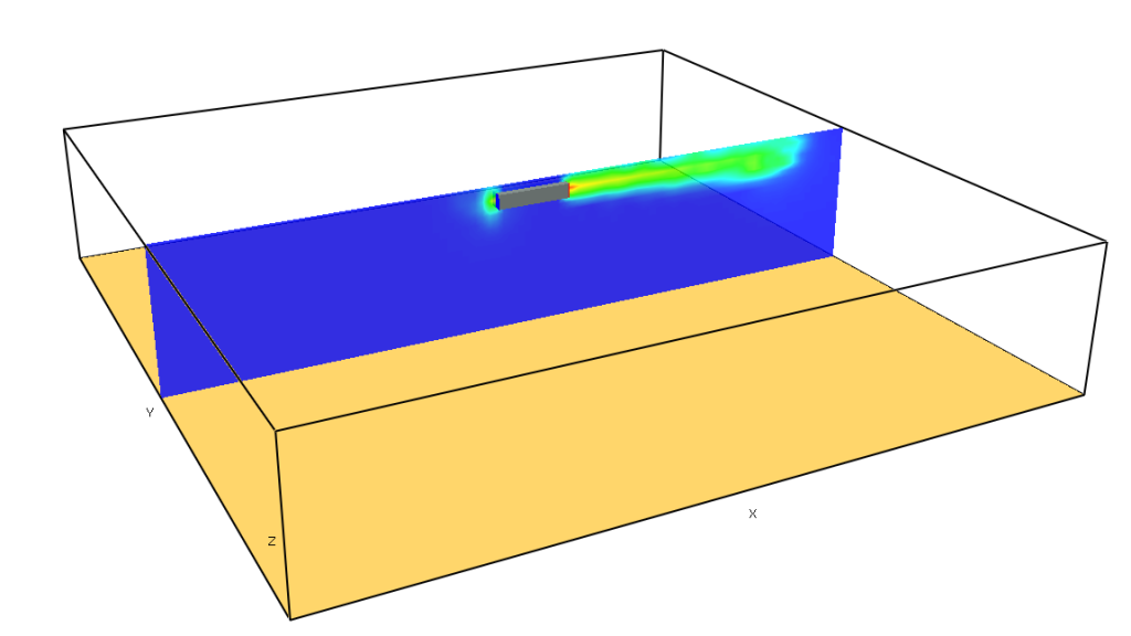
Example of the output of this model is given below. The solid walls of the jet fans are not represented – to do so, add some thin OBST – while the phisical behaviour of generating an thrust and moving flow in one direction is represented correctly.

Method 2 – HVAC
The second jetfan model in FDS is more articulated than the first method but it allows a more generic representations of all types and geometries of jet fans.
&RAMP ID='JFAN1_devc', T=0   , F=0 /
&RAMP ID='JFAN1_devc', T=9   , F=0 /
&RAMP ID='JFAN1_devc', T=10  , F=1 /
&RAMP ID='JFAN1_devc', T=1000, F=1 /

&OBST ID='JFAN1'         , COLOR='COLD GREY', XB=-1, 1, -0.2,0.2, 3.4,3.8 /
&VENT ID='JFAN1_vent_in' , COLOR='BLUE'     , XB=-1,-1, -0.2,0.2, 3.4,3.8, SURF_ID='HVAC' /
&VENT ID='JFAN1_vent_out', COLOR='RED'      , XB= 1, 1, -0.2,0.2, 3.4,3.8, SURF_ID='HVAC' /

&HVAC ID='JFAN1_hvac_in'  , TYPE_ID='NODE', DUCT_ID='JFAN1_hvac_duct', VENT_ID='JFAN1_vent_in' /
&HVAC ID='JFAN1_hvac_out' , TYPE_ID='NODE', DUCT_ID='JFAN1_hvac_duct', VENT_ID='JFAN1_vent_out' /
&HVAC ID='JFAN1_hvac_duct', TYPE_ID='DUCT', NODE_ID='JFAN1_hvac_in','JFAN1_hvac_out', VOLUME_FLOW=1.5, AREA=0.15, RAMP_ID='JFAN1_devc' /
This method is made of three parts:
- RAMP -> in order to represent a time variation of the jet fan thrust this time it is mandatory to use a RAMP command where at different times (T) it is possible to define a coefficient (F) that multiplies the volume flow rate expressed later
- OBST and VENT -> the geometry of the jet fan this time is actually represented by one OBST (solid part) and two VENTs, each of which represent the inlet and outlet of the jet fans. Given this and considering it is possible to define OBST and VENT in any geometrical configuration, this methodology allows to represent also centrifugal jet fans or fans not aligned with the reference system of the CFD analysis
- HVAC -> This command is where the properties of the jet fans are defined. In particular, it is necessary to generate two NODEs, one for the inlet and one for the outlet and a DUCT which connects the inlet and the outlet and where it is possible to define the VOLUME_FLOW in m3/s, the are of the jet fans section and link these properties to the RAMP defined earlier.

CloudHPC is a HPC provider to run engineering simulations on the cloud. CloudHPC provides from 1 to 224 vCPUs for each process in several configuration of HPC infrastructure - both multi-thread and multi-core. Current software ranges includes several CAE, CFD, FEA, FEM software among which OpenFOAM, FDS, Blender and several others.
New users benefit of a FREE trial of 300 vCPU/Hours to be used on the platform in order to test the platform, all each features and verify if it is suitable for their needs

