How is Radiation managed in FDS?
FDS has default settings on how to deal with thermal radiation transport in the simulation.
However, there are some simulations where reducing the ration calculations can be useful to reduce simulation time. Such as per simulation where there aren’t high change in temperature or in external fires. Otherwise, knowing the parameters that manage the FDS radiation solver can help to increase the calculations’ accuracy.
To know more about how radiative transfer is dealt within FDS, check out Ch.16 “Radiation” of the FDS User Guide. The FDS User Guide gives suggestios on which parameter modify from default settings. In order to improve and refine the radiative calculation, at the cost of higher simulation time, or approximate the results at the cost of accuracy. It describes which parameters govern more the sensibility of the radiative calculations.
Radiative Fraction
To understand better how radiation is managed in FDS, the most important concept to introduce is the RADIATIVE FRACTION.
The Radiative Fraction is the fraction of energy release from the fire. Therefore a fraction of fire’s heat release rate, as thermal radiation. It is a function of flame temperature (T4 dependence), fire size, chemical composition of the fuel and combustion products.
Since, in a coarse grid and large fires, the flame temperature and chemical composition can’t be reliably calculated, as the flame cannot be well-resolved because it is approximated depending on the cell’s size of the mesh, the parameter RADIATIVE_FRACTION, on the REAC line, come in handy.
In fact, in order to compensate the underestimation of the fire radiation, the RADIATIVE_FRACTION is set to 35% by default. Therefore, with a settled value of radiative fraction it is possible to specify the fraction of total combustion energy released in the form of thermal radiation.
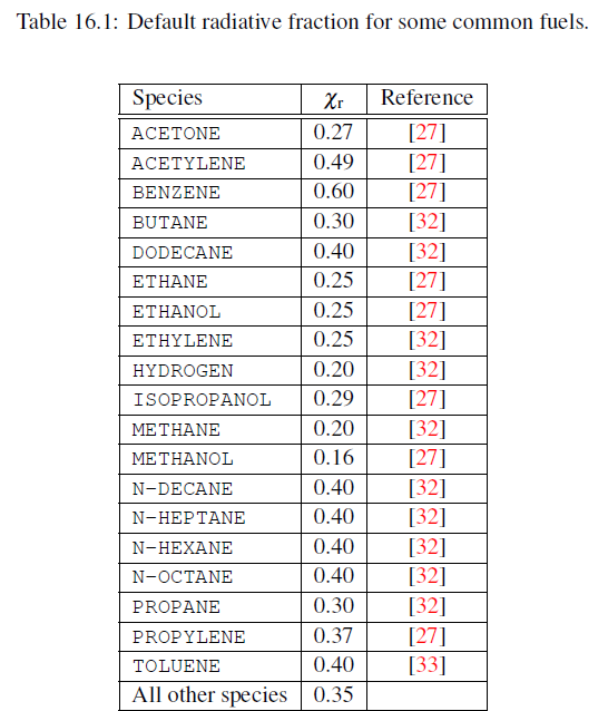
The RADIATIVE_FRACTION is set to a specific value based on the reaction’s FUEL for an LES calculation. Table 16.1 of the User Guide lists the default radiative fraction for some common pure fuels.

The radiative fraction parameter can be set in the FDS script as follow:
&RADI RADIATIVE_FRACTION=0.45 /
Thermal Radiation in FDS
There are four ways of treating thermal radiation in FDS, as thoroughly explored in the FDS User Guide:
- No Radiation Transport
- Optically-Thin Limit; Specified Radiative Fraction
- Optically-Thick; Specified Radiative Fraction (LES Default)
- Optically-Thick; Unspecified Radiative Fraction (DNS Default)
No Radiation Transport
Add in the RADI line the input RADIATION=F and turn off the Radiative Transfer Equation (RTE). In this way you might save more or less 20% of CPU time. Consequently, the radiated energy of the fire disappears form the domain.
This option is useful in scenarios where the changes in temperature are small. If you are simulating a fire with increase of temperature of hundreds of degrees Celsius, you should not run off the radiation transport.
Optically-Thin Limit; Specified Radiative Fraction
Set in the RADI line the absorption coefficient in the RTE, k, to zero by setting OPTICALLY_THIN to T. Therefore, the reabsorption of thermal radiation by cold combustion product gases is neglected.
This option is not recommended for fire scenario in compartments, where it is important to consider the absorption and emission of thermal radiation. While it might be useful for external fires set in a large open space, and it is your interest to calculate net radiation energy transported to targets.
Optically-Thick; Specified Radiative Fraction (LES Default)
This is the default setting of FDS. The RTE transfers energy from hot to cold gasses. The absorption coefficient, k, governs both the emission and absorption of thermal radiation.
Since, the flame temperatures are not well-resolved for coarse grids and large simulations, only for the cells in which the radiative fraction, Xr, times the local heat release rate per unit volume, is greater than 10 kW/m3, the source term in the RTE is adjusted in grid cells.

Therefore, in the fire region, the net radiative emission will be the radiative fraction multiplied by the total combustion energy generated in this region. Elsewhere, the radiative transfer from hot to cold gasses is governed by their bulk temperature and radiative properties, and in particular by the absorption coefficient k.
In order to ably the radiative fraction to the entire domain, and not jut in the cells where the combustion occurs it is possible to change the value of the previous equation form 10 to -1 with the prompt QR_CLIP on the RADI line.
Optically-Thick; Unspecified Radiative Fraction (DNS Default)
In this option it is considered that you can set the radiative fraction to zero, only if you are able to assume that the temperature field and the radiative absorption coefficient and the RTE source term can be well-resolved and calculate without correction. This is the default for a DNS (Direct Numerical Simulation), and you can set it for LES calculations where the grid cells are a few millimeters in size.
In this option, it is important to pursue a proper grid resolution study.
CloudHPC is a HPC provider to run engineering simulations on the cloud. CloudHPC provides from 1 to 224 vCPUs for each process in several configuration of HPC infrastructure - both multi-thread and multi-core. Current software ranges includes several CAE, CFD, FEA, FEM software among which OpenFOAM, FDS, Blender and several others.
New users benefit of a FREE trial of 300 vCPU/Hours to be used on the platform in order to test the platform, all each features and verify if it is suitable for their needs


0 Comments